
Subject Code & Title: BUIL1258 Structures And Materials
Assignment No : Assignment 2
Conditions of Assessment:
1.This is a group assignment to be completed in groups of no more
than 4 students.
2.Students have the option to be marked collectively as a group, or
individually for their individual contributions within the assignment. If students wish to be marked individually, this must be clearly nominated on the cover page of your submission document, and each student’s individual contribution clearly stated. Groups who wish to be marked individually must ensure that each student’s individual contribution is equal (i.e. groups of 4 must ensure that they contribute 25% each).
BUIL1258 Structures And Materials Assignment 2 – RMIT University Australia.

3.Please submit your assignments in PDF format, including the construction programme (please only submit MS Project files if it is absolutely necessary).
4.Please include your group number as part of the file name for any files you submit.
5.Please include your group number on the cover page of the assignment.
6.Students are reminded that cheating, whether by fabrication,falsification of data, or plagiarism, is an offence subject to University disciplinary procedures. Plagiarism is not acceptable. It is also an offence for students to allow their work to be plagiarised by another student or to include names of colleagues/team members who did not contribute to the project.
BUIL1258 Structures And Materials Assignment 2 – RMIT University Australia.

Section 6: Superstructure :
Part A:
Develop a construction programme for the ‘6OO Church Street’ project
Based on the information provided below, and using the drawings in Appendix X as a reference, develop a construction programme for the ‘600 Church Street’ project. Your programme will include the following areas of work:
• Demolition
• Site Establishment
• Retention System
• Bulk Excavation
• Substructure
• Superstructure
• Formwork Stripping
• Concrete Patching
• Post-Tension Reinforcement Stressing and Grouting
Use the following table of activities to programme the works:


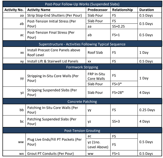
The superstructure activities above are for 1 no. level only (Basement 2). Using the example above, programme the remainder of the superstructure works accordingly.
Please ignore the Mezzanine Level as shown on the drawings, and proceed directly from GF – Level 1.
Activity xx can commence once the roof slab (pour 2) is poured.
Activity yy can commence following the pouring of the suspended slab above that level of in-situ walls. For example, the in-situ core walls constructed as per activity 16 can be stripped once activities 16 and 21 are complete (3 day lag following slab pour).
Activity ww can commence following final stressing of the post–tension tendons to a given suspended slab (activity ac) and following completion of form work stripping to the suspended slab one level above where grouting works are due to commence. For example, if the post-tension tendons have been fully stressed on the Level 1, Pour 1 slab, grouting works can commence once the Level 2, Pour 1 slab has been stripped. (*Lag times for form work stripping refers to calendar days – not working days)
Format:
• Construction programme must be in the form of a Gantt Chart showing the relationships between activities. MS Project recommended.
• The date of completion of all works must be clearly reflected in the Gantt chart
• For the purpose of this exercise the superstructure works will be considered complete when all form work materials are stripped out all post-tension works are complete, and all concrete patching works are
complete
Additionally complete the following table as part of your submission document:
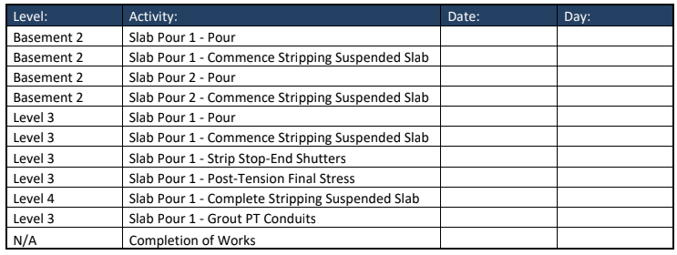
• ‘Complete’ refers to the final date/day of the individual activity
• ‘Commence’ refers to the first date/day of the individual activity
Section 7: Jump form Systems
Part A:
Modify your construction programme for the ‘6OO Church Street’ project to reflect construction of an in-situ concrete core
Based on the construction programme you have developed in section 6, replace the precast concrete core with an in-situ concrete core and modify your programme to include the following:
• Construction of the building’s core using a jump form system
You must also include the following:
• Assembly and installation of the jump form system
• Dismantling and removal of the jump form system
Use the following table of activities to programme the works:

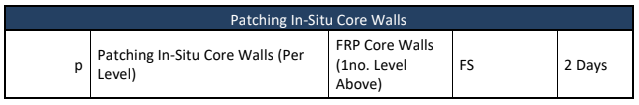
Construction of the in-situ core must remain at least 1 no. full level above construction of the rest of the superstructure at all times. For example, activity jba must be complete construction of in-situ core walls between B 2 – B 1 before construction of the Basement 2 suspended slab can commence.
Disassembly of the jump form system must be complete before construction of the roof slab can commence.
Patching works to a given level of the core can commence once the core walls one level above are poured. For example patching can commence between Levels 2 – 3 once the core walls between levels 3 – 4 are poured. Patching works can continue whilst the jump form system is being disassembled.
Installation of lift and stairwell lid panels can commence once the roof slab (pour 2) has been poured.
Format:
• Construction programme must be in the form of a Gantt Chart showing the relationships between activities. MS Project recommended.
• The date of completion of all works must be clearly reflected in the Gantt chart
• For the purpose of this exercise the superstructure works will be considered complete when all form work materials are stripped out all post-tension works are complete, and all concrete patching works are
complete
Part B:
Compare the difference between construction of the building’s core using precast panels and using a jump form system
Based on the construction programmes you have developed in both section 6 and Part A of Section 7, and using the information provided, write a brief report outlining the differences between construction of the building’s core using precast panels and fully in-situ construction using a jump form system. Discuss the following in your report:
• Construction programme
• Construction cost
• Logistics
Precast:
Using the architectural and structural drawings* in Appendix Y, and the table below, calculate construction costs for construction of the core using precast panels:

The supply rate for precast panels allows for the offsite manufacture and transport of all panels to site.
*As per the structural design, the core incorporates a combination of precast panels and some in-situ wet-joints and walls between B 3 – L 4. For the purpose of this exercise, please ignore the in-situ components of the core.
Jump form System:
Use the jump form pricing document in Appendix Y to calculate construction costs for constructing the core in-situ using a jump form system.
You must allow for the following items when calculating the costs for a jump form system:
• Lump sum hire cost
• Weekly hire rate for hire components (wall shutters & hydraulics)
• Weekly hire rate for external access stairway
• Engineer certificate
• Transport:
o 5no. visits to site to deliver jumpform system
o 5no. visits to site to remove jumpform system
o Transport is charged at $1,250/visit
• The hire period will commence on the day activity j (Assemble Jump form System commences
• The hire period will end on the day activity jx is complete Dis assemble Jump form System
There is a minimum hire period of 15 weeks for hire components wall shutters & hydraulics. Any hire period beyond 15 weeks must be calculated and accounted for on a pro-rata basis as per the relevant rate in the jump form pricing document.
There is no minimum hire period for hire of the external access stair way.
BUIL1258 Structures And Materials Assignment 2 – RMIT University Australia.
Section 8: Fall Protection
Part A:
Develop an installation and climbing sequence for a perimeter screen protection system for the 6OO Church Street project
Based on architectural drawing A220 and using the screen climbing sequence drawing in Appendix Z as a guide develop an installation and climbing sequence for a perimeter screen system for the 600 Church Street project. Use detailed sketches to illustrate the sequence of works involved based on the following criteria:
• Construction of 8 no. levels of suspended slabs (Level 1 – Roof Level)
• Screens initial 9980mm sections are installed following construction of the 1st suspended slab at Level 1
• Screens must be fixed to the Level 1 slab using:
o 2no. needles per screen
o 2no. raking-props (push-pull props) per screen
• Initial 9980 mm sections cannot be installed more than 9100 mm above the 1st suspended slab top of screen cannot be above this height
• Extensions 3980 mm sections can be installed once there are 2no. levels of needles 2 no. needles per screen per level engaged to the initial screen sections
• Perimeter fall-protection of at least 1800 mm must be provided to the live deck once the initial screen sections have been installed. At least 1800 mm of fall protection must then be maintained at all times to the live deck for the duration of the works
• The screen system must provide fall-protection to at least 4no. levels of the superstructure once it has been fully installed initial screen +extension section
• There must be 3 no. levels of needles engaged 2 no. needles per screen per level in order to jump the system vertically
On the northern elevation of this project, the slab profiles vary considerably between Level 1 – Roof Level. For the purpose of this exercise you do not need to consider the slab profiles consider the slab-to-slab heights only.
Part B:
Quantify the perimeter-screen protection system costs for the 6OO Church Street project
Based on your construction programme from Section 6, your installation and climbing sequence from Part A and the screen pricing document in Appendix Z quantify the total costs for the perimeter-screen protection system based on the following:
• The hire period will commence on the day of the Level 1, Pour 1 slab pour
• The hire period will end 14 days following the Roof Level, Pour 2 slab pour
• Total length of perimeter-screen system required is 125 linear metres
• The total number of screens required is 51
• 1 no. semi-trailer truck can transport:
BUIL1258 Structures And Materials Assignment 2 – RMIT University Australia.
o 5 no. 9980 mm sections (per load)
o 10 no. 3980 mm sections (per load)
o All screen accessories (per load)
Section 9: Temporary-Works Engineering; Form work; Precast Concrete
Part A:
Discuss 3 no. areas of the construction process for the 600 Church Street project where temporary-works engineering is required
Nominate 3 no. areas/construction processes where temporary-works engineering is required during construction of the structure for the 600 Church Street project. Discuss why temporary-works engineering is required for these areas.
Part B:
Research and nominate 3no. different types of proprietary horizontal form work systems that could be used to construct suspended concrete slabs Research and nominate 3 no. different types of proprietary horizontal form work systems that could be used to construct a suspended concrete slab (at least 200 mm thick).
You must provide the following information for each:
• The name/model number of each system
• The manufacturer of each system
• An image of each system
• The maximum load-capacity of each system
Part C:
Research and nominate 3 no. different types of anchors which could be utilised for precast panel braces
BUIL1258 Structures And Materials Assignment 2 – RMIT University Australia.

Research and nominate 3 no. different types of anchors which could be used to fix the foot of a precast panel brace to a concrete slab. Each of the products must comply with testing requirements as per AS3850.1:2015 (Prefabricated Concrete Elements). You must provide the following information for each:
BUIL1258 Structures And Materials Assignment 2 – RMIT University Australia.
• The name/model number of each anchor
• The manufacturer of each anchor
• A section image of the anchor system installed to a concrete slab
• The maximum working load limit of the anchor system at a given concrete compressive strength
Excellent Assignment Help
We Aim At:
- Lowest Price.
- 100% Uniqueness.
- Assignment Fastest Delivery.